
PCOM Access Guide For VisiLogic
The following application note illustrates how to implement the PCOM and INFO mode password function blocks. The additional ladder diagram functions show one way of implementing these security functions; however, it is the responsibility of the user to ensure that their implementation meets the security level they are expecting or desire.
Unless you are very sure of what you are doing, we do not recommend downloading this to a remote PLC as the download will result in a potential loss of comms.
With the release of VisiLogic 9.9.0 Unitronics have added in new security measures to deny access to unwanted outside sources. To achieve this, Unitronics have now given the user ways to disable areas on the VisiLogic PLC so that only trusted people can access the areas they need to.
Because of this, there will now be compiling errors on your program (if using ethernet Communications) due to not having the function blocks on your project now as shown below.

This Guide will show you the step-by-step guide on setting up PCOM Password and Info Password.
(Example Project: ‘VisiLogic PCOM Set Up.vlp’)
Setting your PCOM (Ethernet) Password
For this guide we will be attempting to set up so that we can communicate to the plc to upload a new project through ethernet.
Where as before all you needed to achieve this was this:
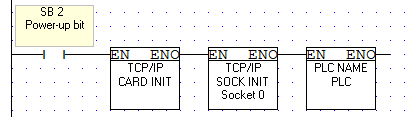
We now need to add two new function blocks to make this work.
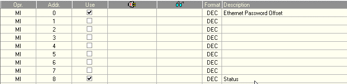
For now, we will focus on setting up your PCOM Password which is located under Com>TCP/IP>Set PCOM (Ethernet) Password. Add this new function block to your power-up rail with A= an register that has between 1-8 registers spare after it like this:
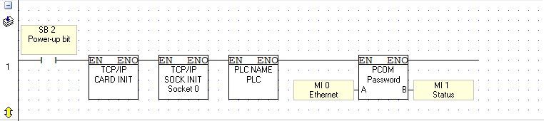
The reason we have left space here is because the PCOM password requires Ascii Input.
The Ascii input you will be entering will need space for two characters per one register. For example, in this program i4Automation as an ethernet password would be separated as follows: (Passwords are case sensitive)
| Letters in registers | HEX Value | Hex Breakdown |
| MI0= i4 | 3469 Hex | 34=4 69=i |
| MI1= Au | 7541 Hex | 75=u 41=A |
| MI2= to | 6F74 Hex | 6F=o 74=t |
| MI3= ma | 616D Hex | 61=a 6D=m |
| MI4= ti | 6974 Hex | 69=I 74=t |
| MI5= on | 6E6F Hex | 6E=n 6F=o |
Conversions can be done here:
https://www.rapidtables.com/code/text/ascii-table.html
From here we can choose to enter the ascii values in as power values to each of the MI’s and that would have a set password that can not be changed unless you go online through VisiLogic and change it.
Instead, we want to be able to change this password on the PLC itself on its HMI.
Go to your HMI and input a new Ascii string from the toolbar on the left shown below:
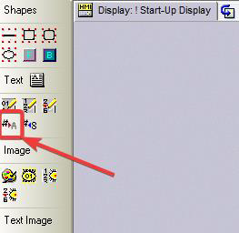
Draw its box as you would a numeric value box onto your chosen screen and then click onto the box to reveal the properties’ menu of the variable ascii string.
Example of window:
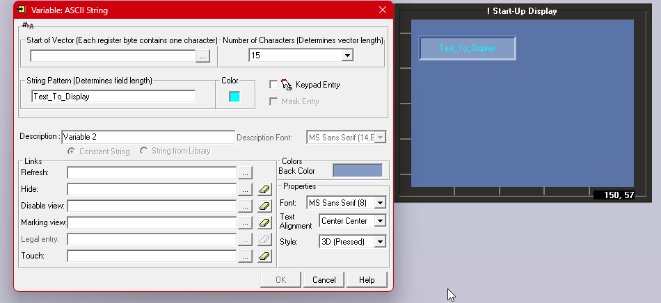
Please see below where you should enter in details and what each box is for:
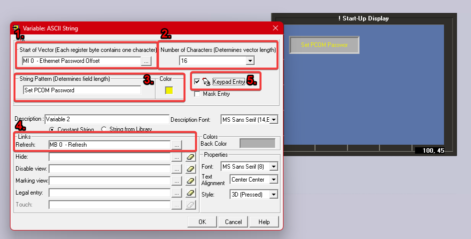
- Start of Vector – select which register value the vector will start from.
- Number of characters – how many characters the password will be and also how many registers will be needed for the password between 8-16 long (2 characters= 1 register)
- String Pattern – used to show what text is displayed in box before input.
- Refresh – link Variable to a Bit to refresh the Variable.
- Keypad entry – Tick this to enter the password you require.
Optional: Mask Entry – This is underneath Keypad Entry and this allows you to mask the input used for the password.
Setting Info Password
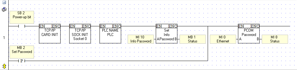
After pressing ok, I can now set up a button to set the password on every press instead of just on power up and also add in the new info password function block. To do this go to Utils>Set Info Mode Password in your ladder and apply it to the power up rail also like shown:
For this example, we will be only having the Info mode working off its power up value but you can edit the numeric value by adding a numeric FB on the HMI linked to the MI relevant and type in a new value and setting with a button similar to the PCOM Password layout above.
To achieve a power value, see example below: (this example will use the new password of 1568 as shown)
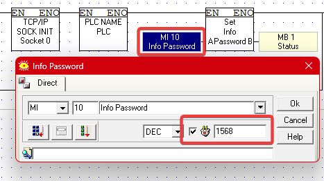
Please note: Passwords such as 2222,3333,4444 do not work and won’t be accepted!
Now download this project into your PLC and you should see that after entering a new password into the box you are able to connect via Ethernet!
More Examples:
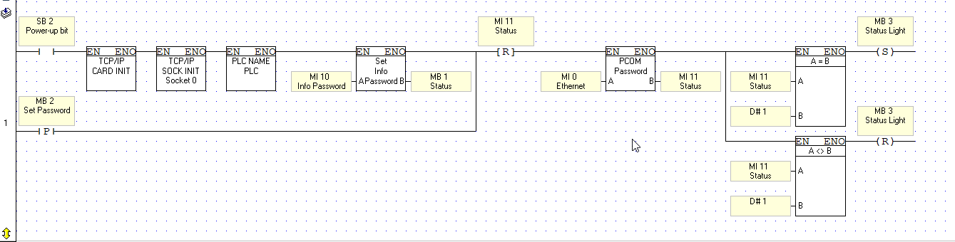
There are different ways to show this also. By adding a binary image/switch to the status of the PCOM password FB we can have a visual on if there is a connection ready to be used also shown below:
Extra Information
- With this new security update the default port of 20256 that comes with every PLC can still be used and accessed but is now no longer recommended to use. A list in the hyper link below shows a lit of port numbers that can be used instead:
https://en.wikipedia.org/wiki/List_of_TCP_and_UDP_port_numbers#Registered_ports